
Tooling Development for Aluminum Die Casting
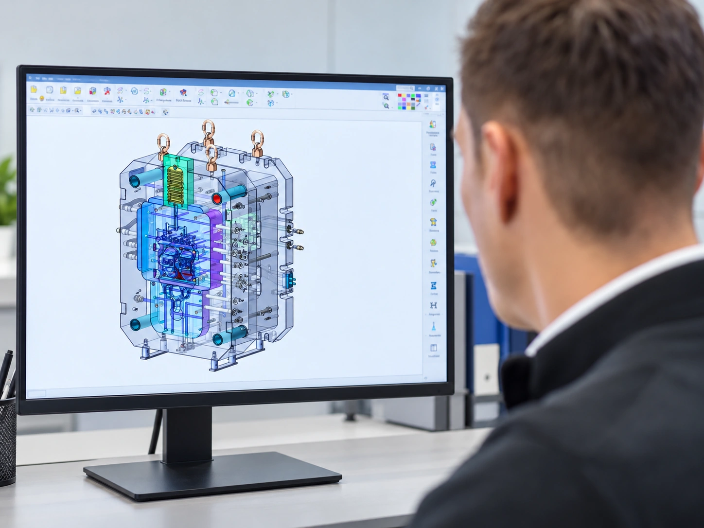
Tooling development connects the component design with its casting and machining requirements. Start with the drawing, functional features and expected production volumes.
01 / MANUFACTURING SERVICEWhat we discuss
- Component drawings and functional features
- Production requirements and project scope
- Machining allowances and downstream operations
Define the tooling brief.
Plan the tooling around the part geometry, functional interfaces and expected quantities. Include machining and finishing needs in the same brief.
- 01Component geometry
- Mark mating features, ribs, openings and areas where the tooling design needs particular attention.
- 02Production requirements
- Provide the expected order quantity, annual demand and trial-sample requirements, where known.
- 03Secondary operations
- Identify machined surfaces, finish requirements and protected interfaces before defining the tooling scope.
- 04Project scope
- Agree tooling responsibilities, the sample review process and the information required before the next stage.
From design review to trial samples.
Confirm tooling responsibilities, trial-sample requirements and the sample review process before planning the next stage.
- 01
Share the component design
- 02
Discuss tooling considerations
- 03
Agree the project scope
Connected services.
Explore the other stages in the manufacturing process.
Have a component
in mind?
Bring the part drawing, tooling scope and trial-sample requirements.